Installation instruction for
Contact-Duo-Profiles
Installation instructions
Installation instructions for Contact-Duo-Profiles as exemplified by a
profile without compensation chamber and without sealing lip
0
Tools required
Rubber scissors, knife, electronic side-cutter, sandpaper (grain size 80), belt punch,
pointed pliers
1
Cutting the profile to size
1.1 Cutting the profile to length
Total length of the switching strip minus 34 mm for the end caps (17 mm per cap).
When cutting to size, make sure the cut edges are straight, smooth and right-angled.
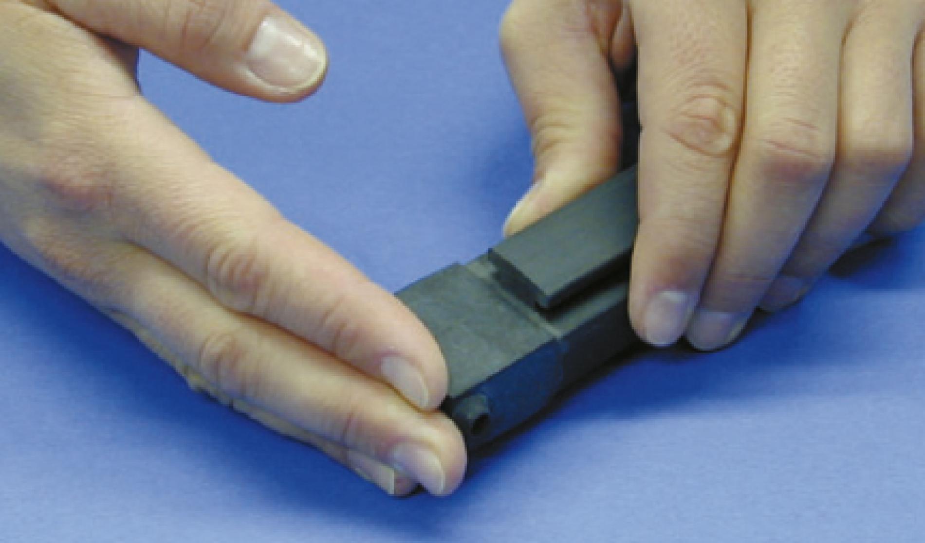
2
Shortening the foot by the dimension of the end cap’s circumferential
edge
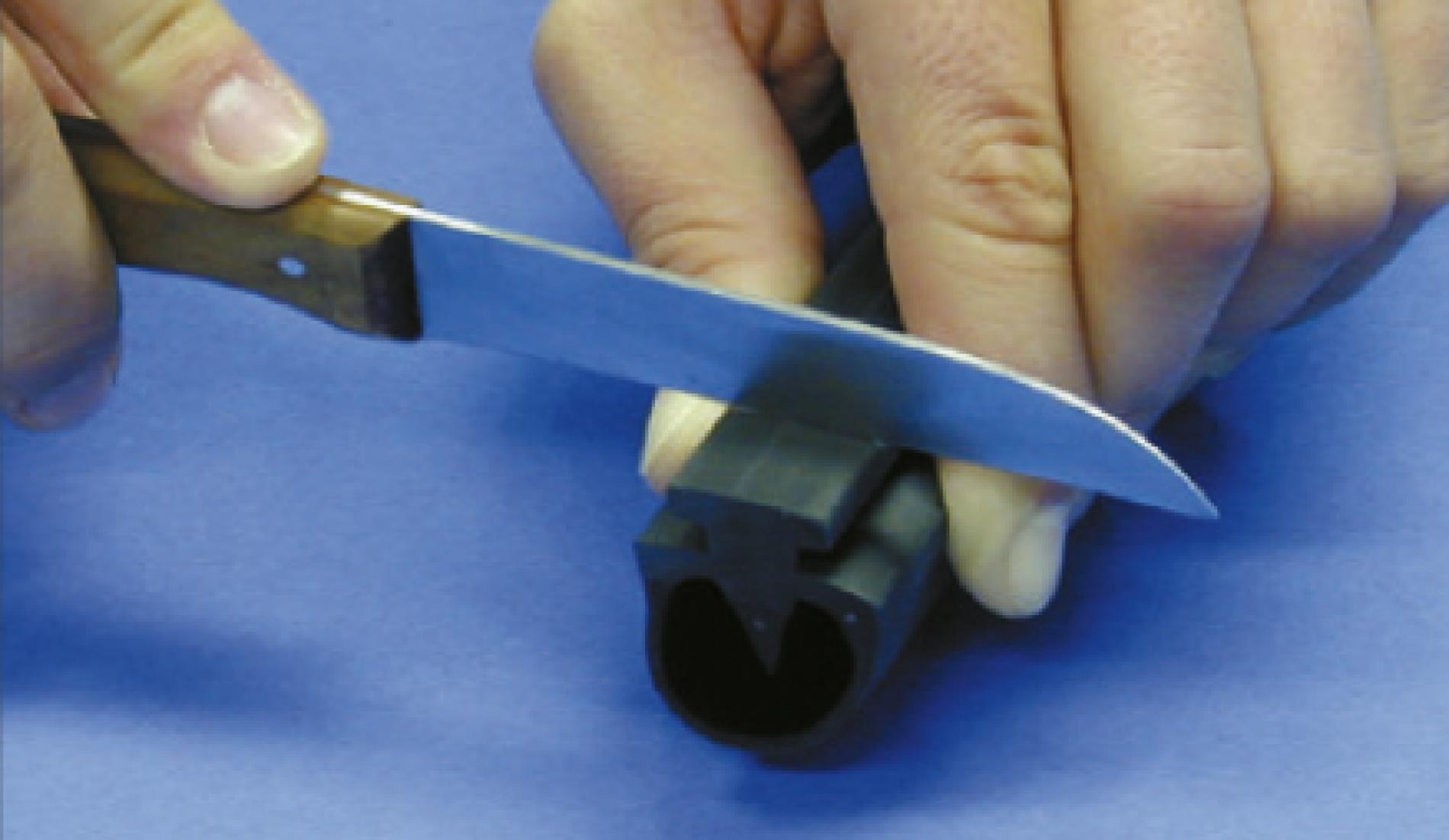
2.1 Right-angled cross-section
Cut at right angles into the foot after 12 mm.
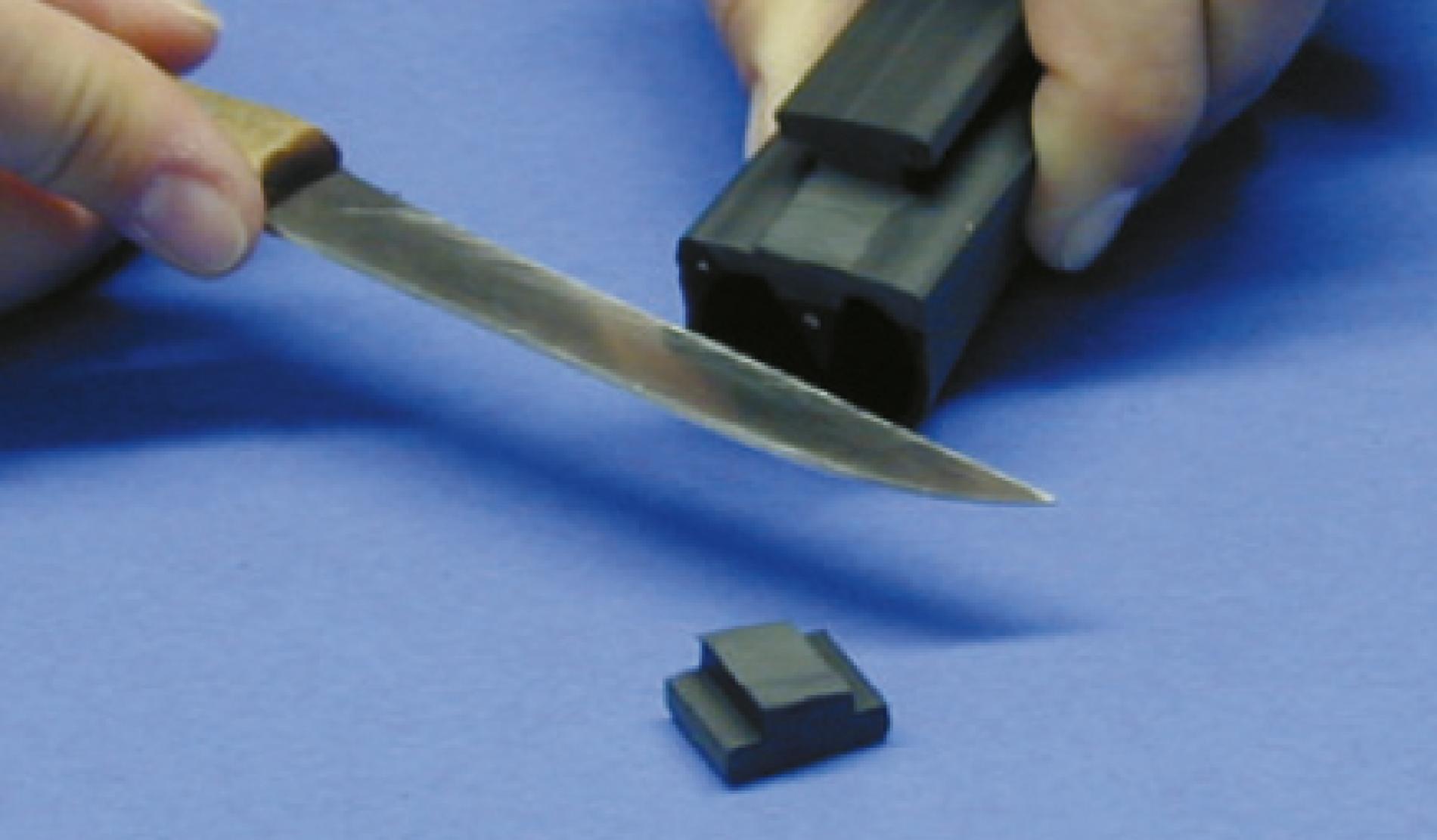
2.2 Axial cross-section
Cut off the foot after 12 mm up to the right-angled cut. Any protruding remains of the foot will have to be sanded off later.
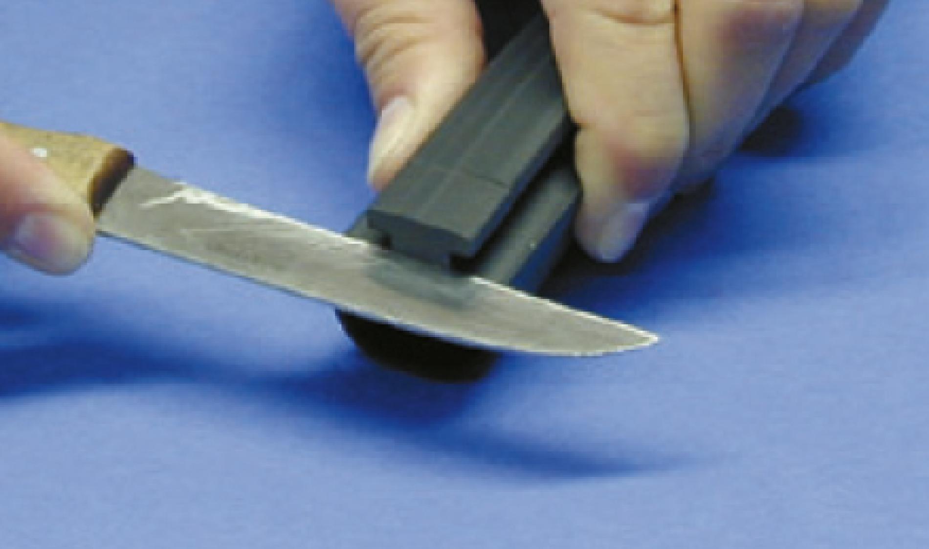
Take care to ensure that you do not damage the profile when making the rightangled cut.
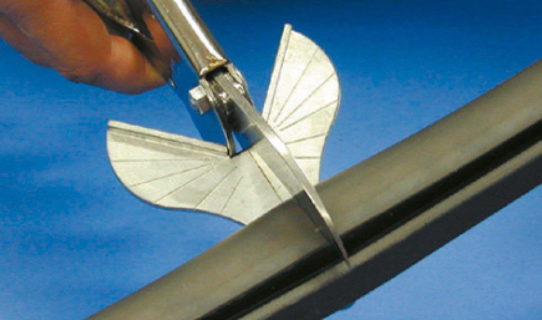
3
Shortening the copper wires
3.1 Shortening
Shorten the copper wire with flush precision.
This step enables you to achieve a smooth sanding surface.
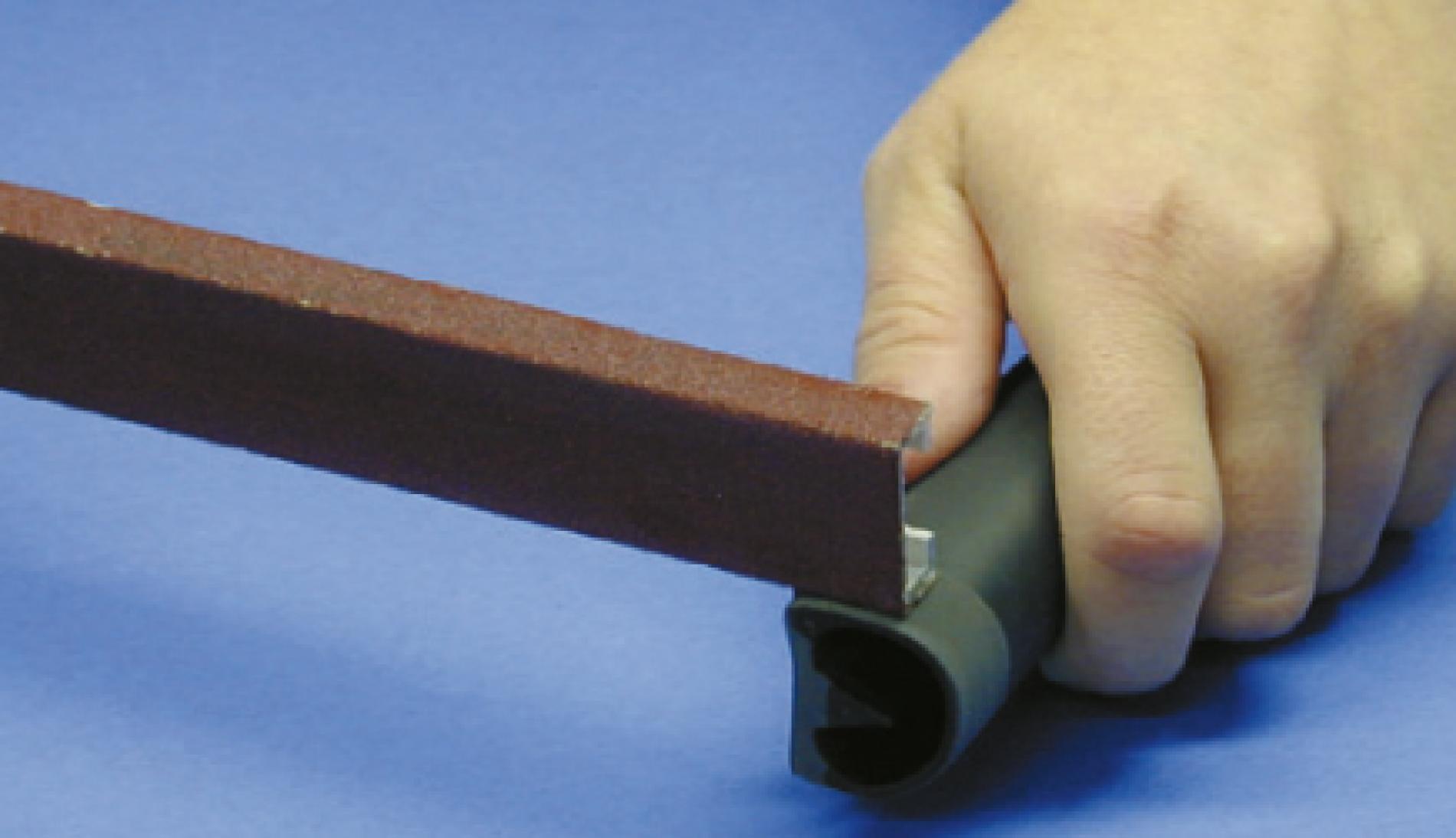
4
Sanding the profile
4.1 Cut surface
Sand the cut surface until it is even and matt.
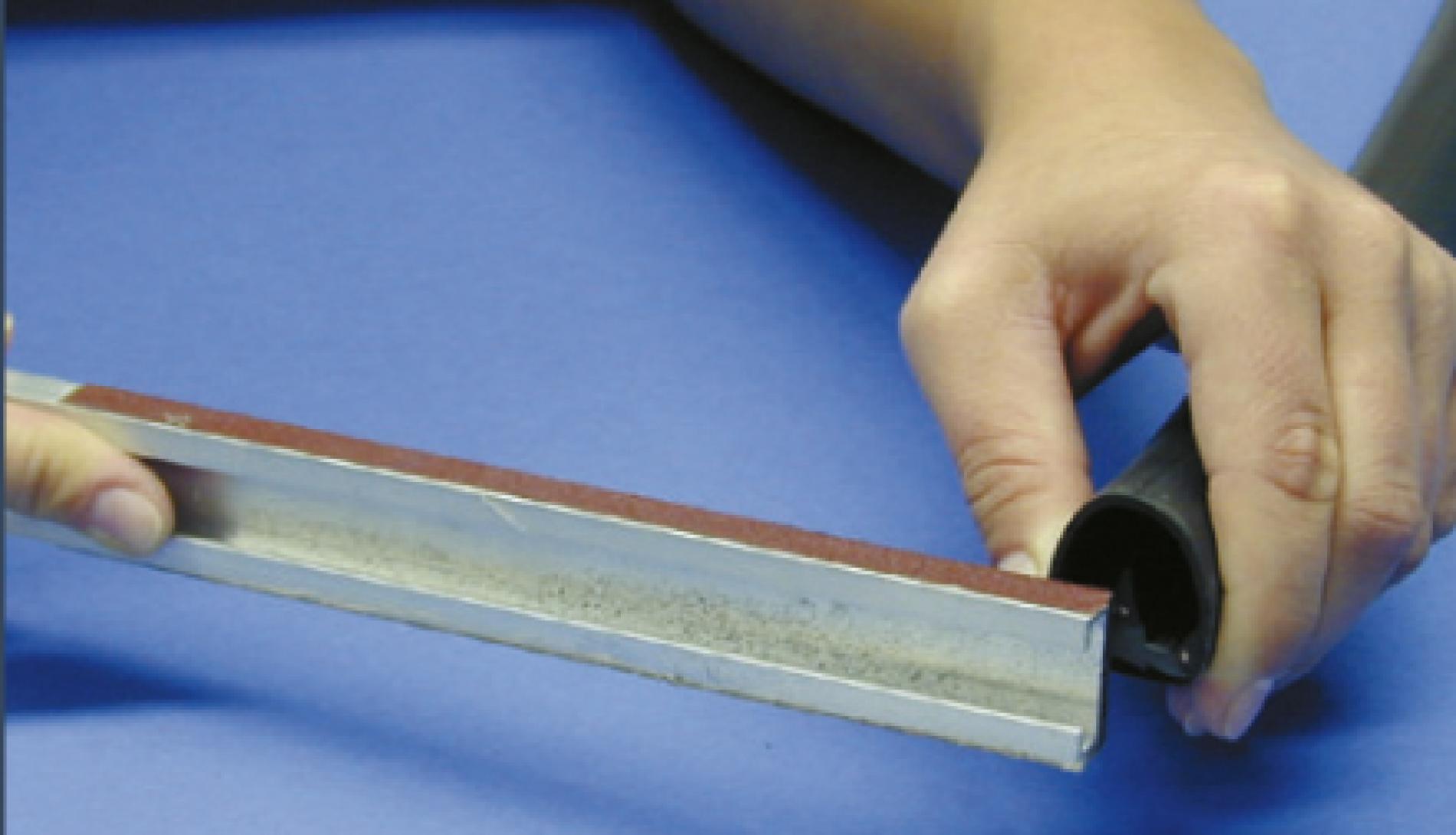
4.2 Profile foot
The remaining rib of the profile foot must be completely sanded until it is even.
4.3 Switching head
Sand the surface of the switching head to the width of the circumferential edge (at least 12 mm) until it is matt.
Important: the edges must not be sanded until they are round. Straight-cut edges guarantee reliable adhesion. During this procedure, take care to ensure that soiling (grinding dust, foreign bodies, adhesive, etc.) does not penetrate into the switching chamber.
Sanding the end of the profile prepares the surface for gluing.
5
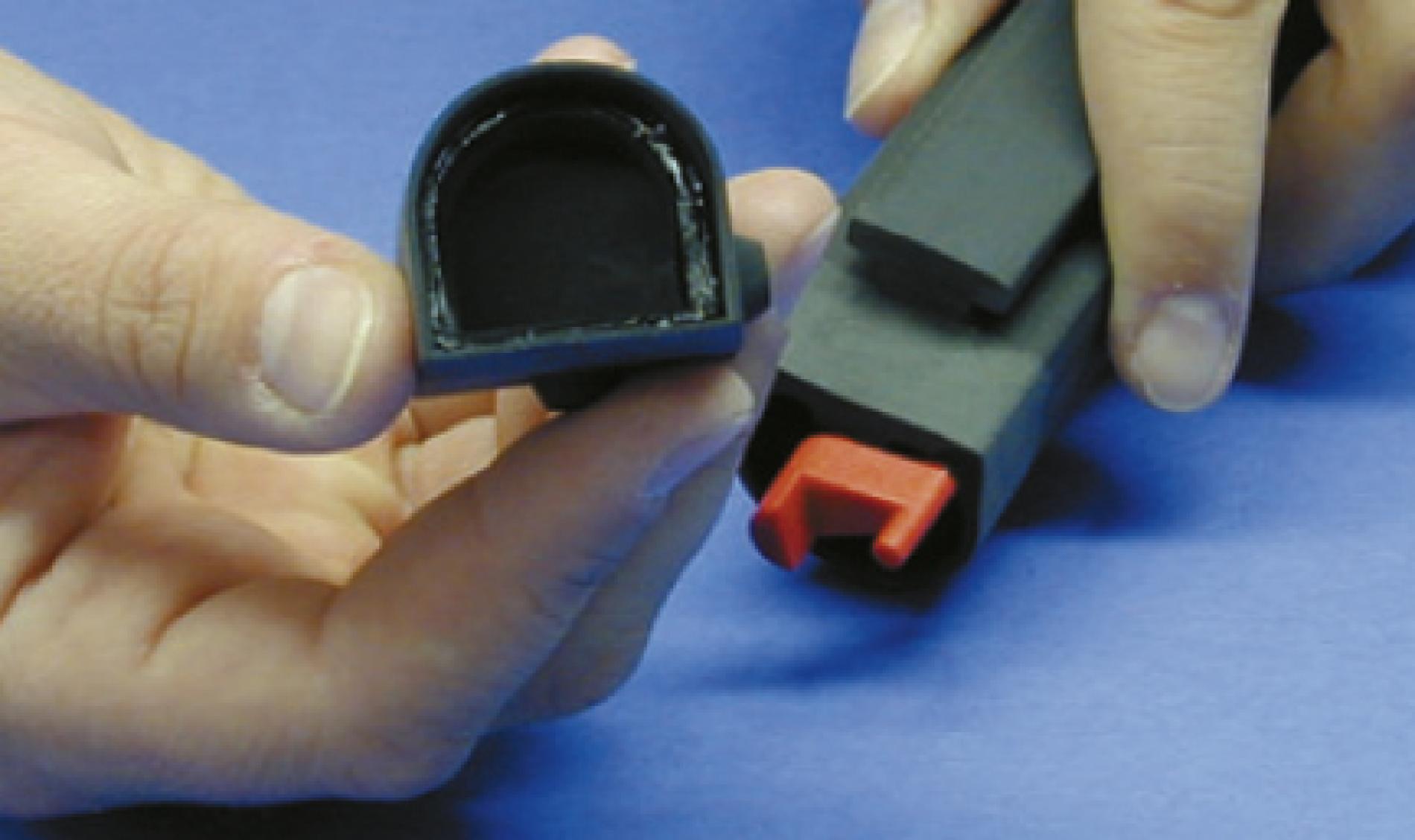
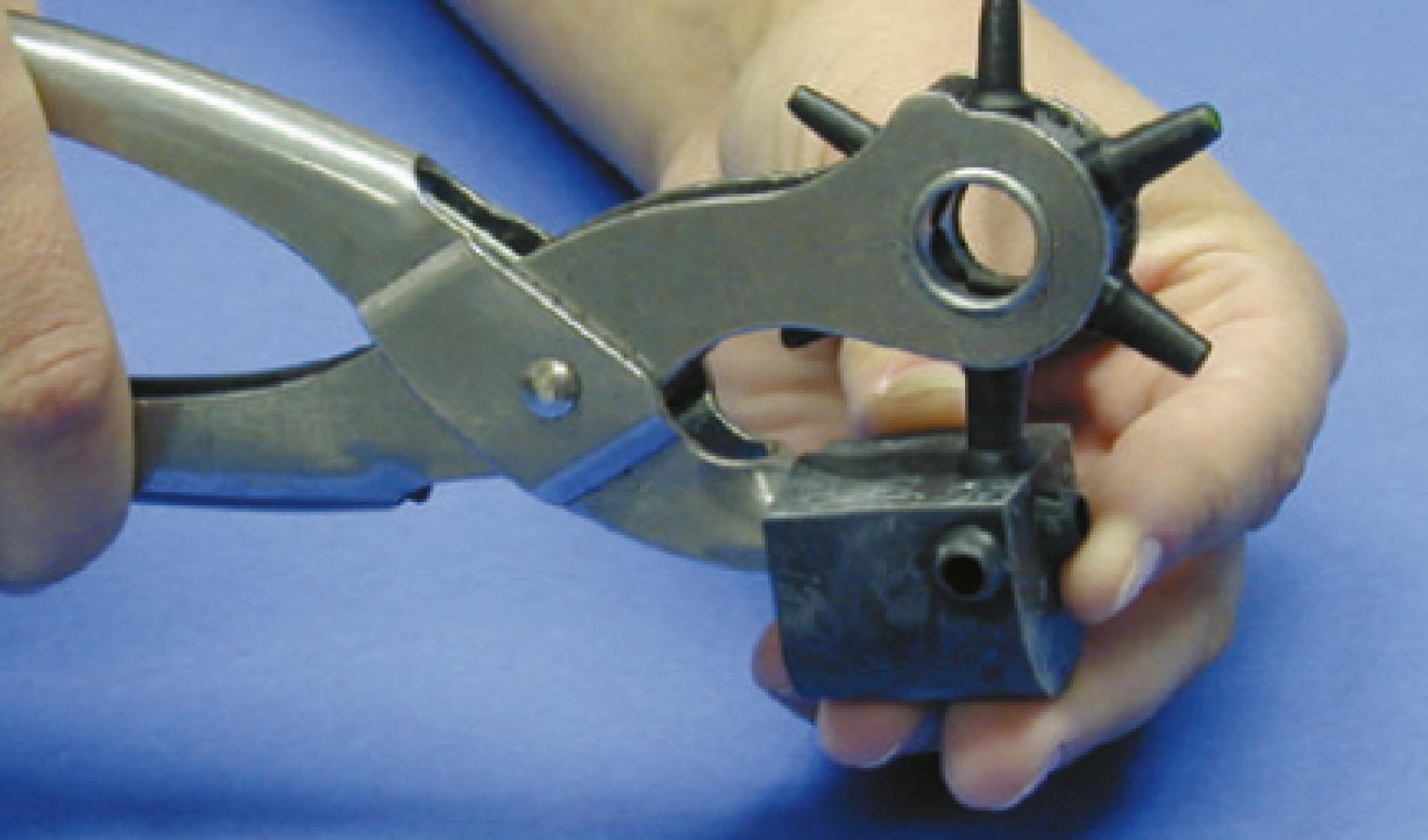
Preparing the end cap for the connecting cable
5.1 Opening the cable bushing
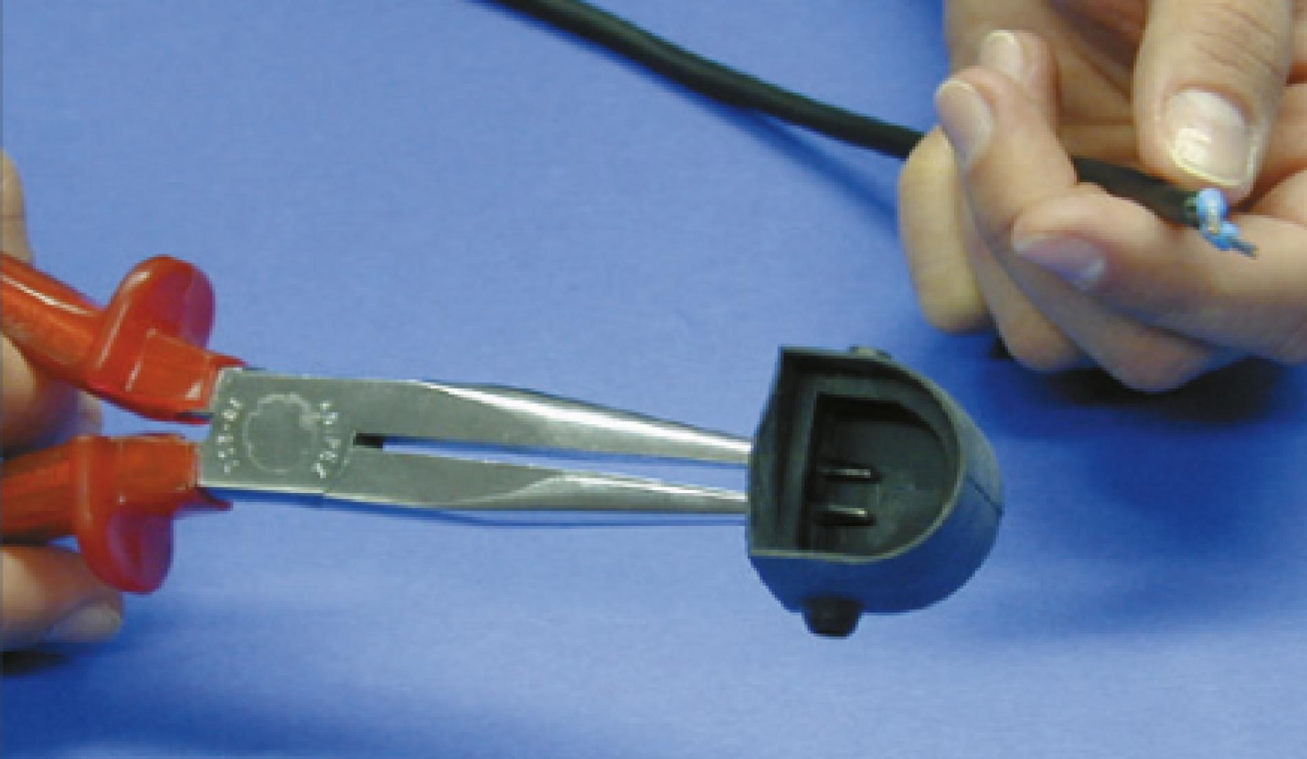
The cable bushings are closed inside. In accordance with the type of connection involved, open the desired bushing with a belt punch (pipe 4.5). Remove the remaining closure, using pointed pliers if necessary.
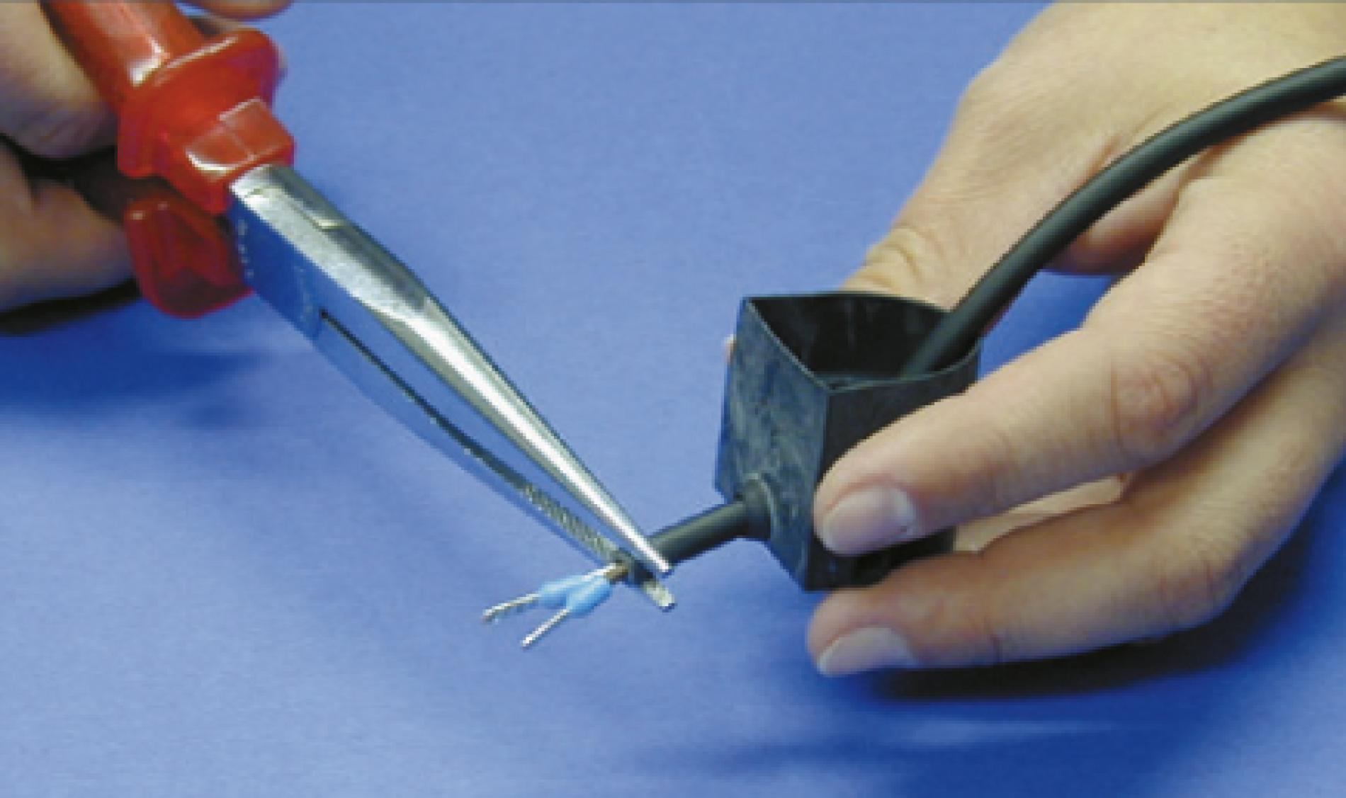
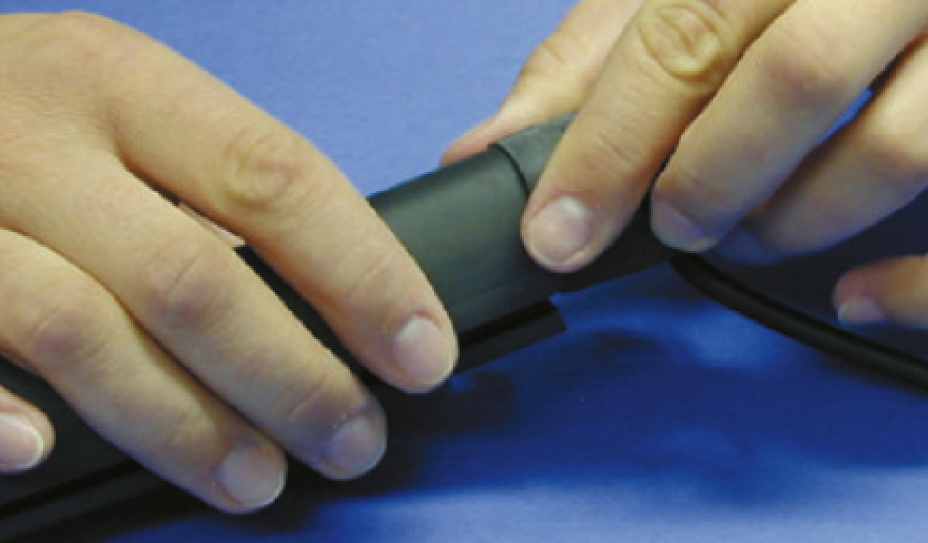
5.2 Pulling through the cable
Pull the connecting cable in through the perforated cable bushing until shortly before the cap, using pointed pliers if necessary.
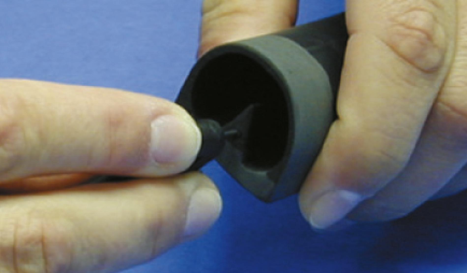
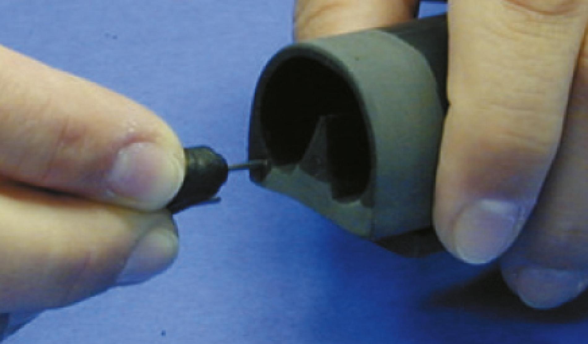
Insert the spike of the belt punch precisely into the cable bushing, taking care not to damage the bushing.
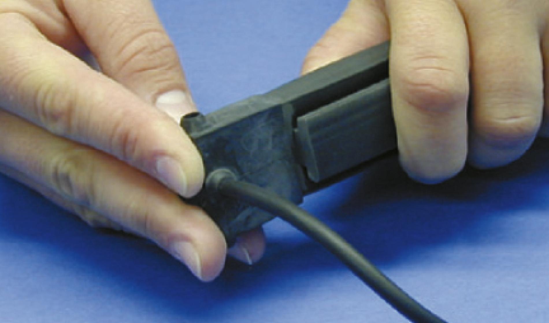
6
Inserting the plug connector with the connecting cable
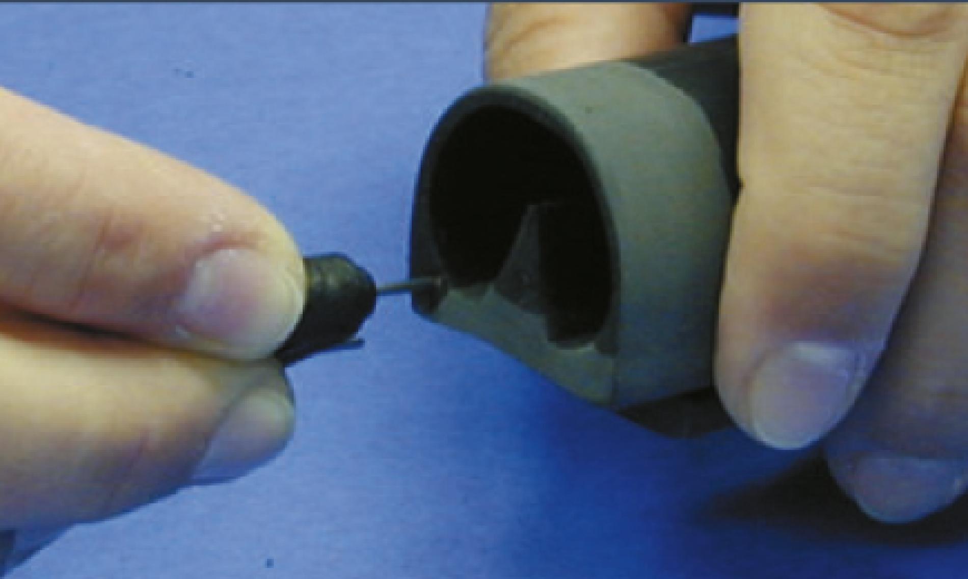
6.1 Prepunching
Use the needle of the terminating plug connector to prepunch in the centre of the top and bottom copper wires.
6.2 Insertion
Now plug the plug connector with the connecting cable into the prepunched copper wire.
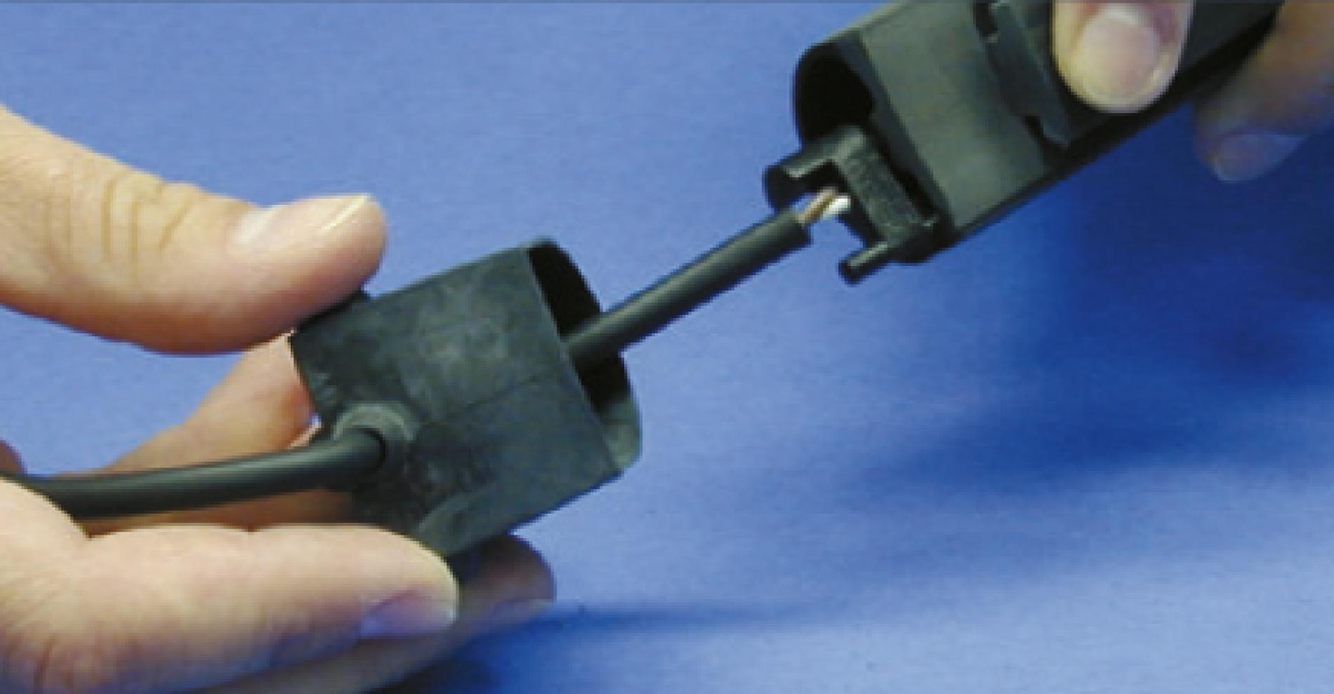
The plug connector must be inserted in the centre of the copper wires, so as to ensure reliable contacting.
The tapering end of the plug connector must face outwards and the round side towards the switching wedge. Only in this configuration will the cap close properly.
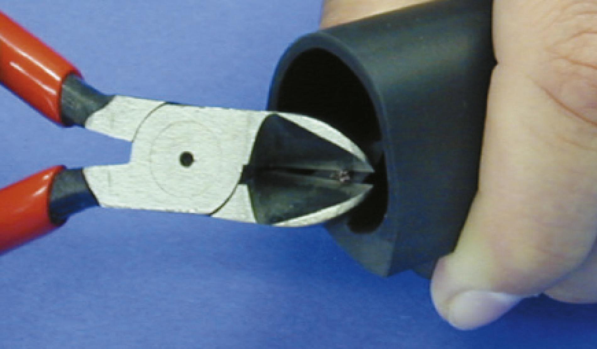
In the case of a cable exiting at the side, the corresponding spacer must be removed at the plug connector on the cable outlet side, using a side-cutter. Be careful of parts flying off! Wear eye protection.
7
Wetting the interior rib with adhesive
7.1 Wetting
Apply a thin but even film of adhesive to the rib. Applying too much adhesive will impair the adhesion properties.
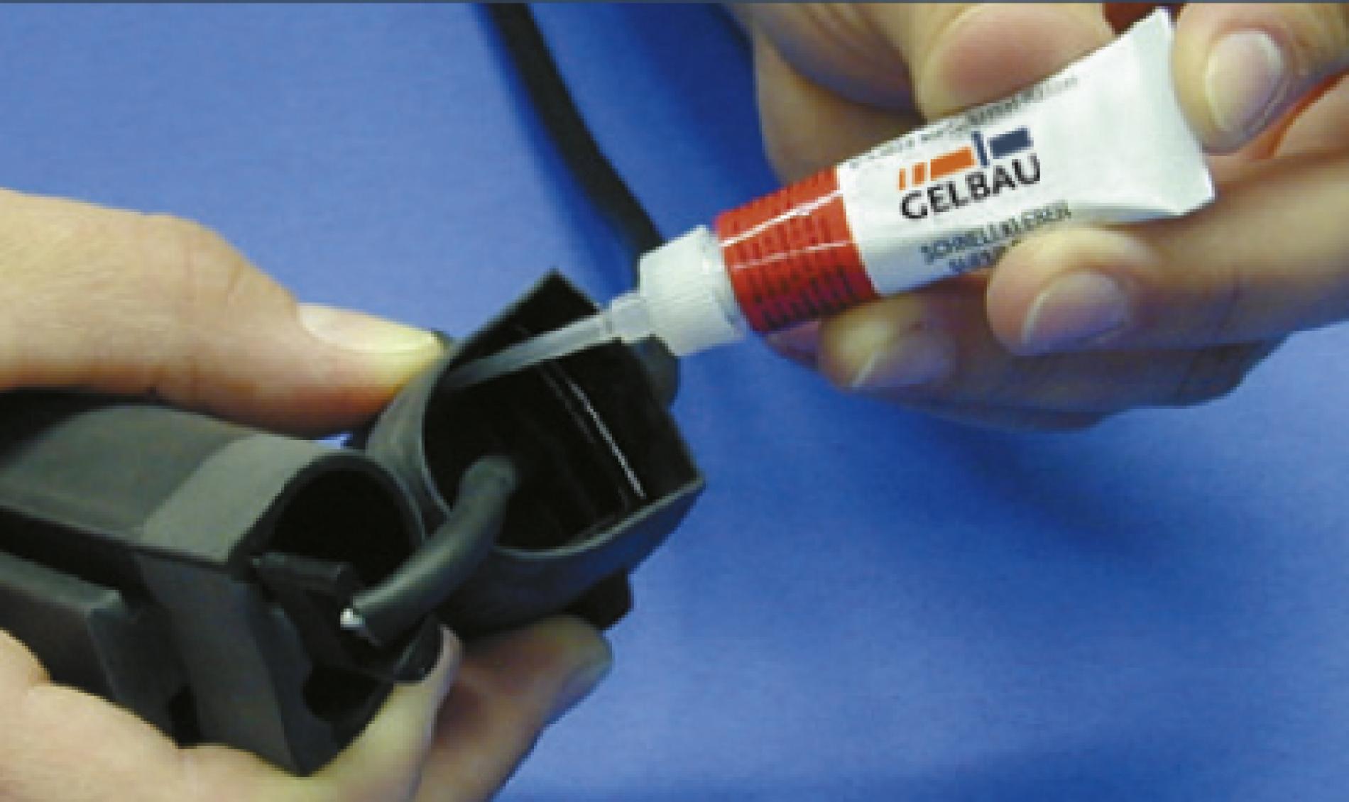
Important: when wetting the rib with adhesive, make sure that no adhesive gets onto the inner sealing edge of the end cap and on the cable of the plug connector. The adhesive sets immediately, and then it will no longer be possible to shift the parts.
Use the adhesive with the utmost care. Avoid any contact with skin and eyes, and always comply with the safety instructions on the tube.
Only our adhesive is matched to the components involved.
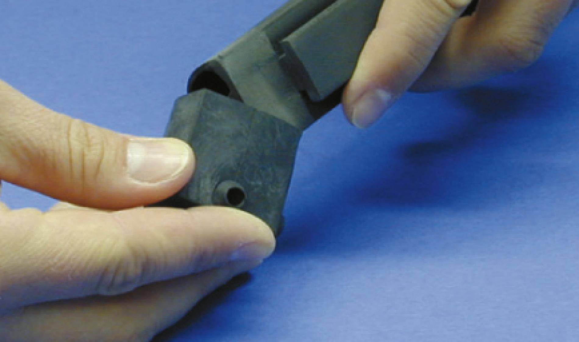
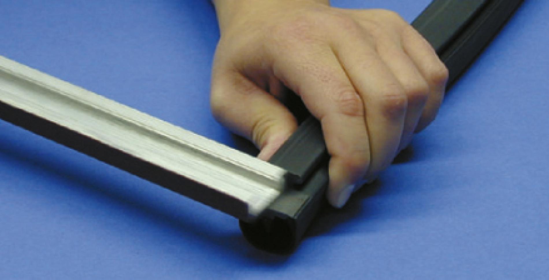
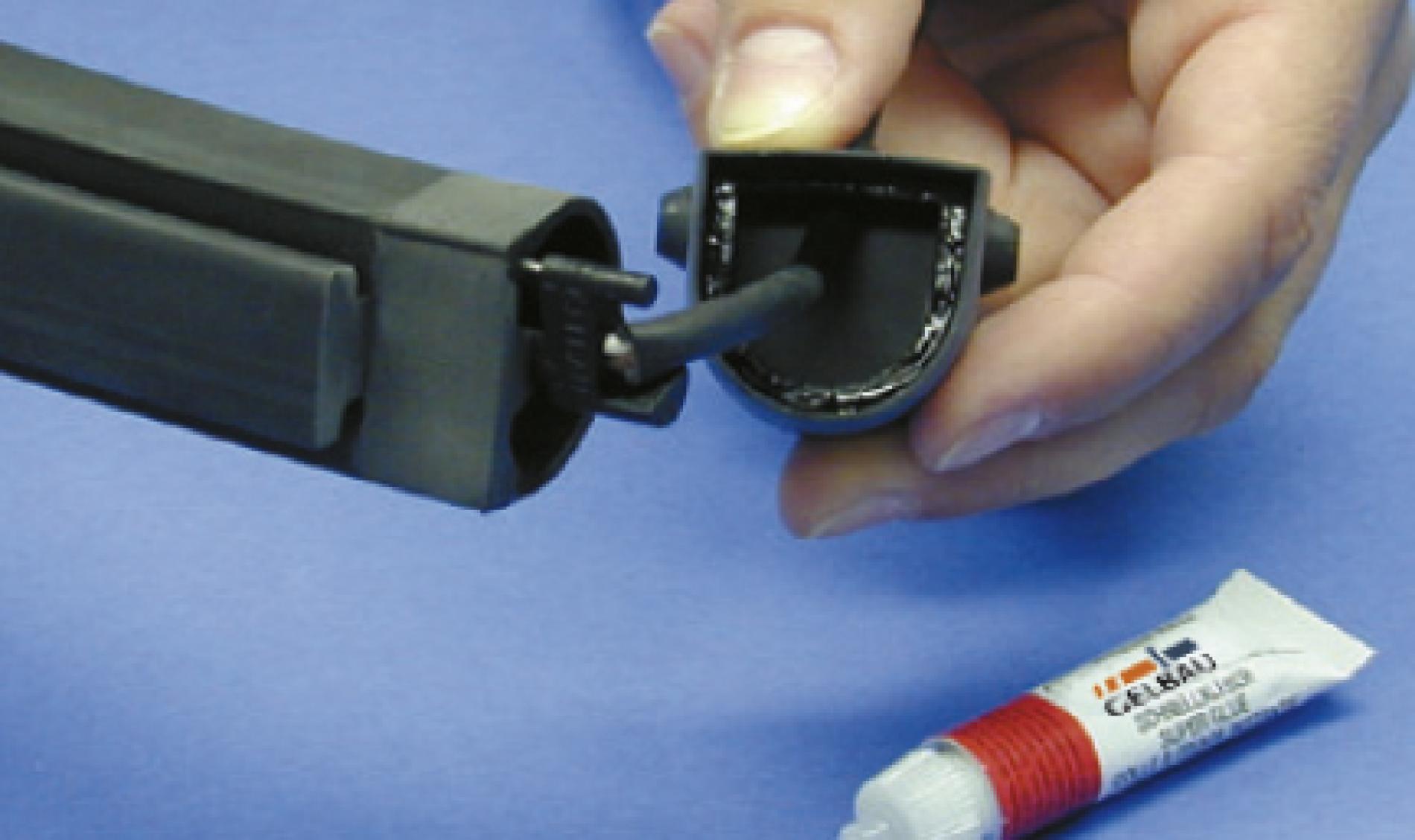
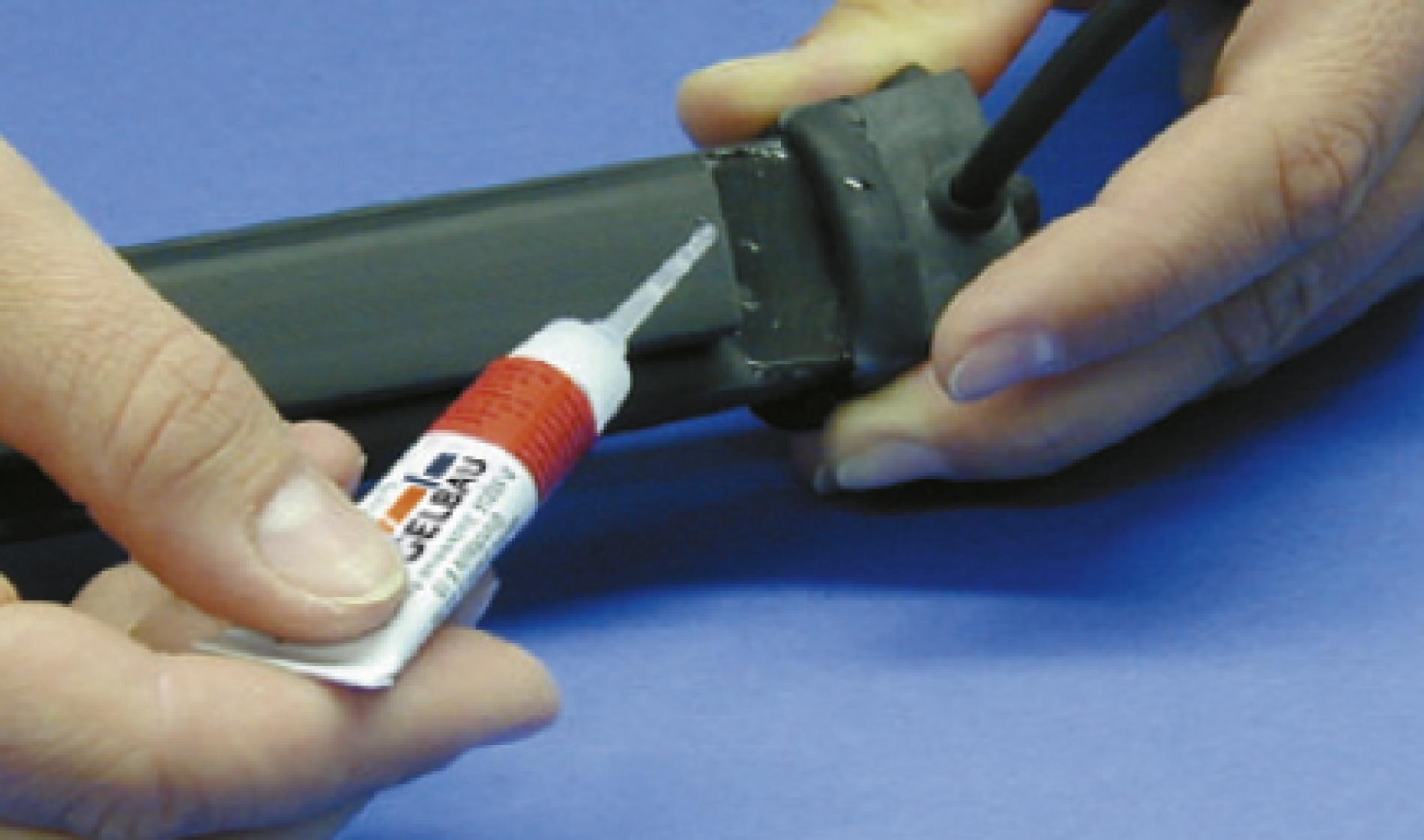
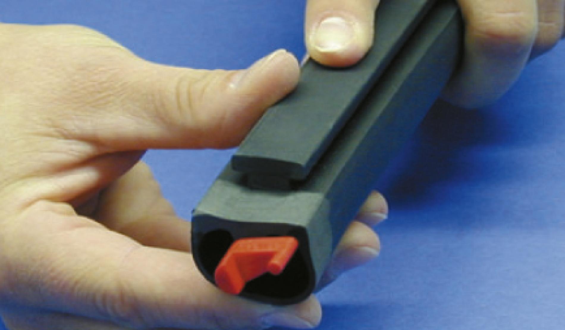
8
Fitting the end cap
8.1 Fitting
Place the end cap on the profile from the profile foot side. It is particularly important to make sure the corners are positioned correctly, so that the cap does not jam when being pushed on. Then press the cap firmly for about 10 seconds. Only a short time should elapse between applying the adhesive and pressing on the cap.
When fitting the cap, the cable must also be pulled through the bushing, without withdrawing the plug connector from the copper wires. We recommend practising this procedure several times without adhesive. With adhesive, there will no longer be any opportunity to make a correction.
When practising, repeatedly pull the plug connector approx. 50 mm out of the end cap again, then plug the plug connector into the copper wires, and then fit the end cap.
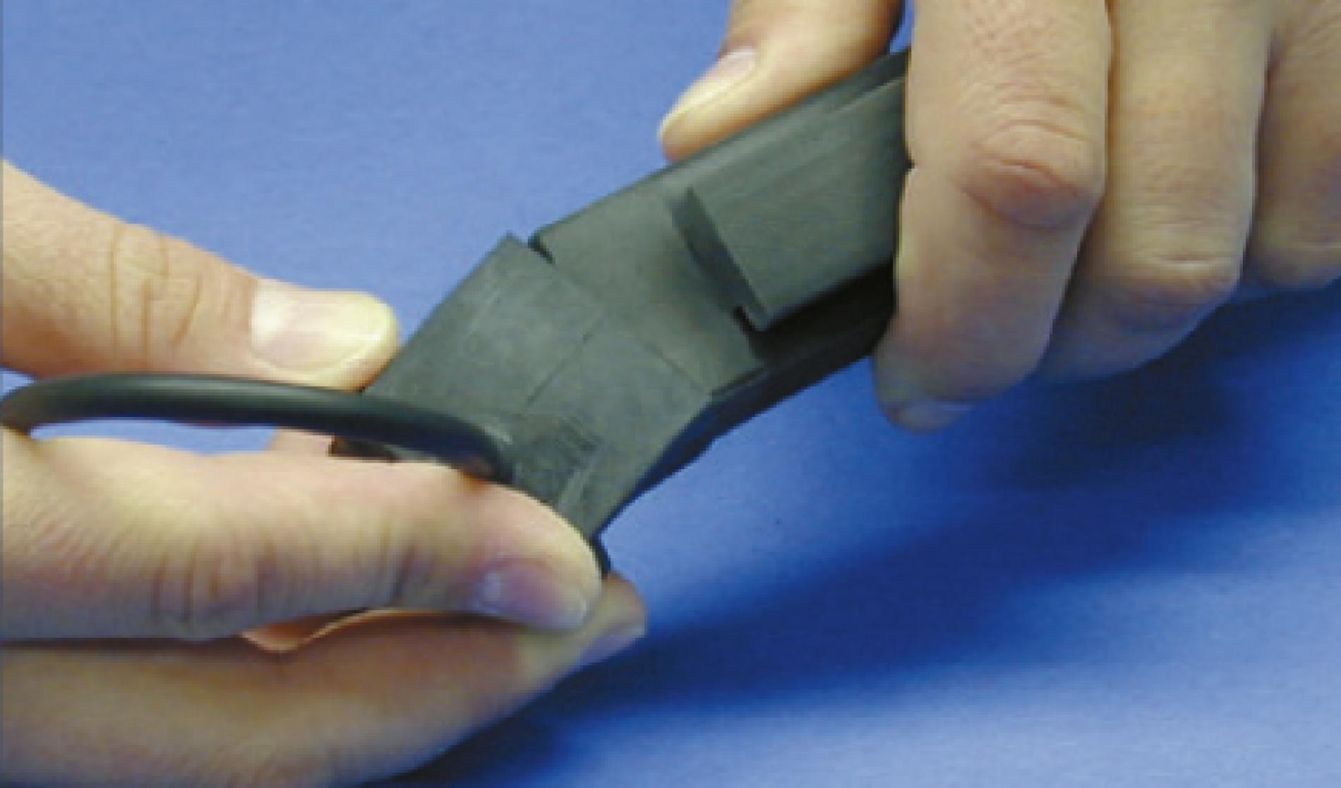
9
Gluing the end cap in place
9.1 Gluing on the foot side of the profile
Fold back the circumferential edge and apply a thin, even film of adhesive to the adhesive surface of the foot. Fold the sealing edge back into position, first press the two corners down so that the end cap cannot shift, and for approximately 10 seconds press onto the entire adhesion surface.
9.2 Gluing the switching chamber
Fold back the circumferential edge, and apply a thin, even coating of adhesive to the right or left half as far as the centre, all the way into the corners. Fold the circumferential edge back into position and for approx. 10 seconds press the adhesion surface. Then fold back the circumferential edge again and likewise spread the other half with a thin, even film of adhesive right into the corners. Fold the circumferential back into position, and once more press the adhesion surface for approx. 10 seconds.
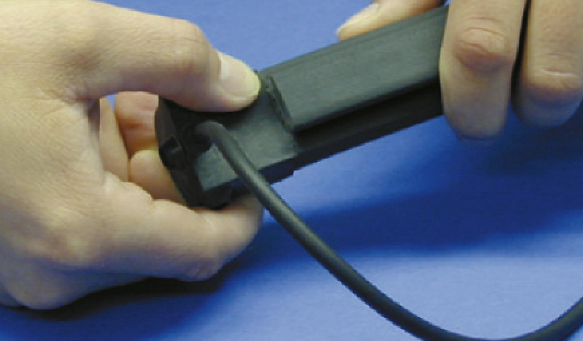
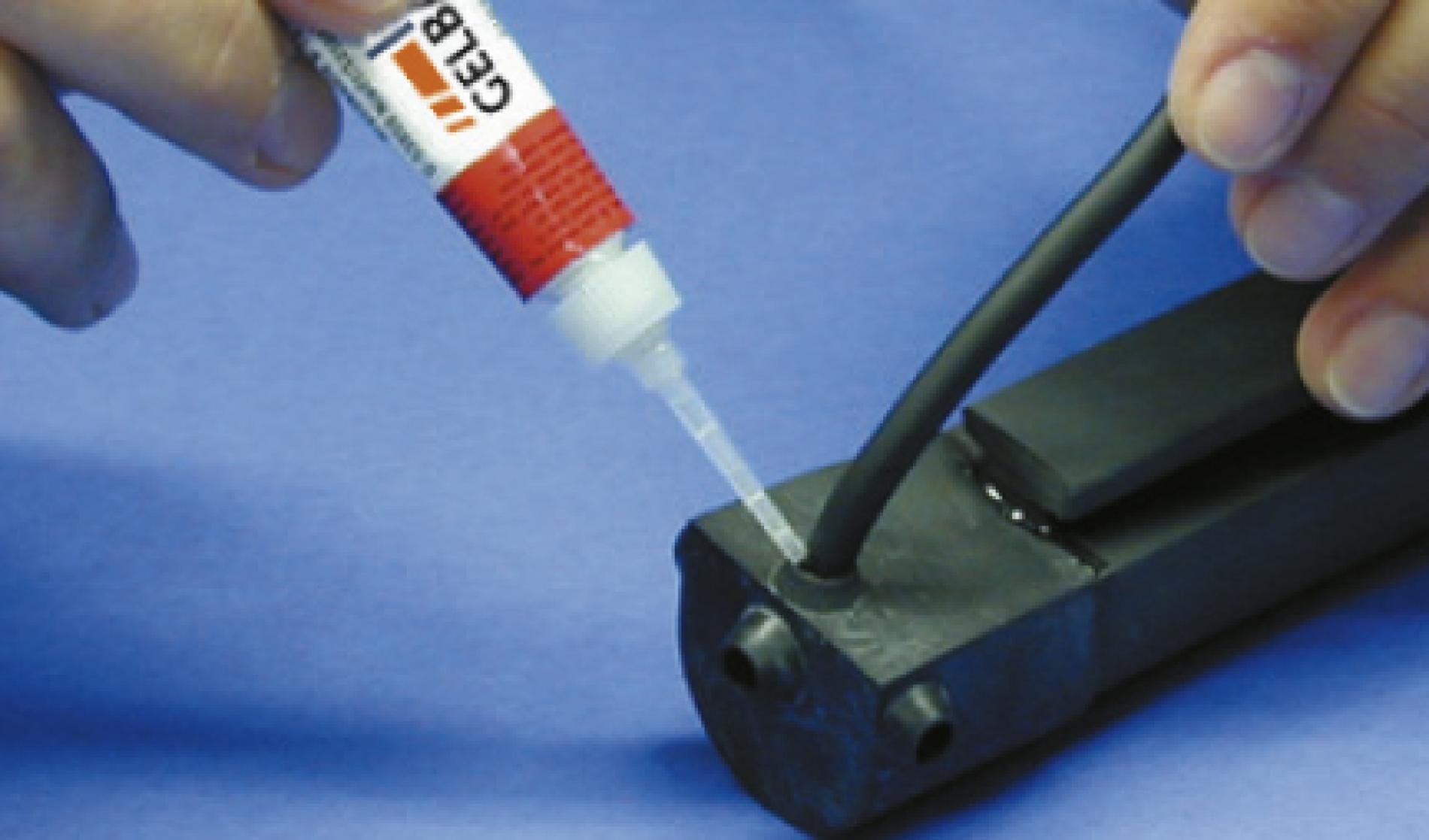
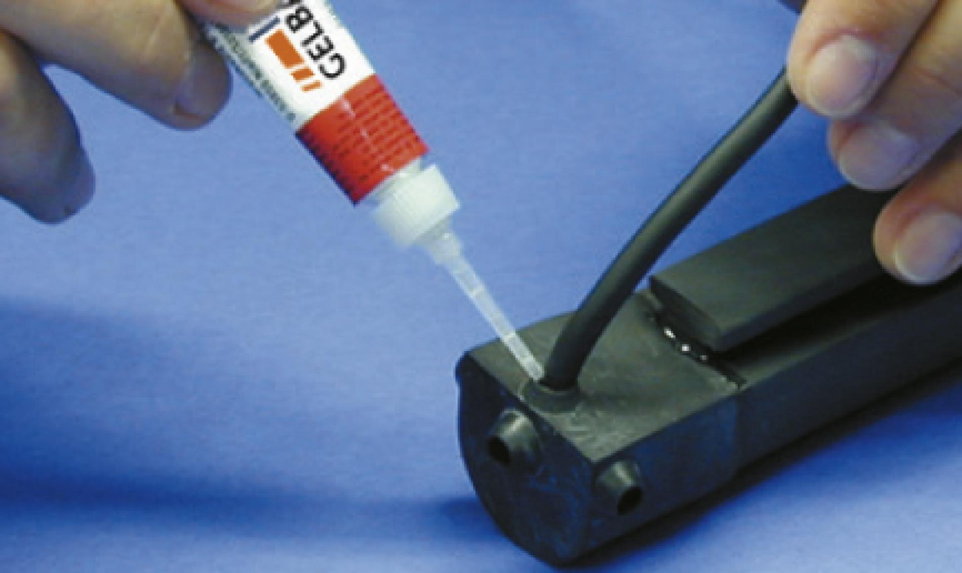
9.3 Gluing the cable exit
Carefully bend away the cable protruding from the bushing and allow the adhesive to run into the bushing around the cable.
10
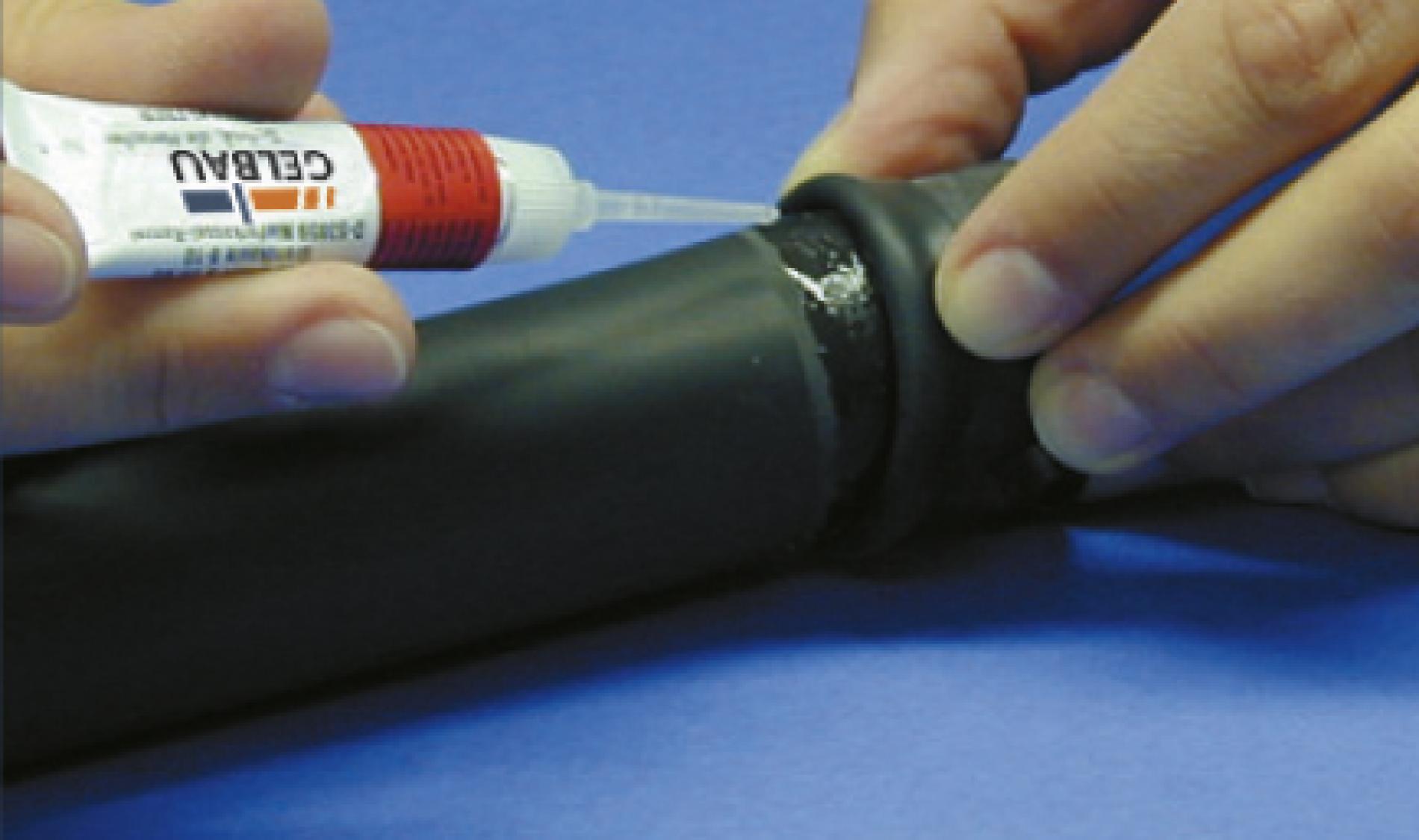
Sealing
10.1 Sealing the end cap
Apply a thin film of adhesive to the edge of the end cap
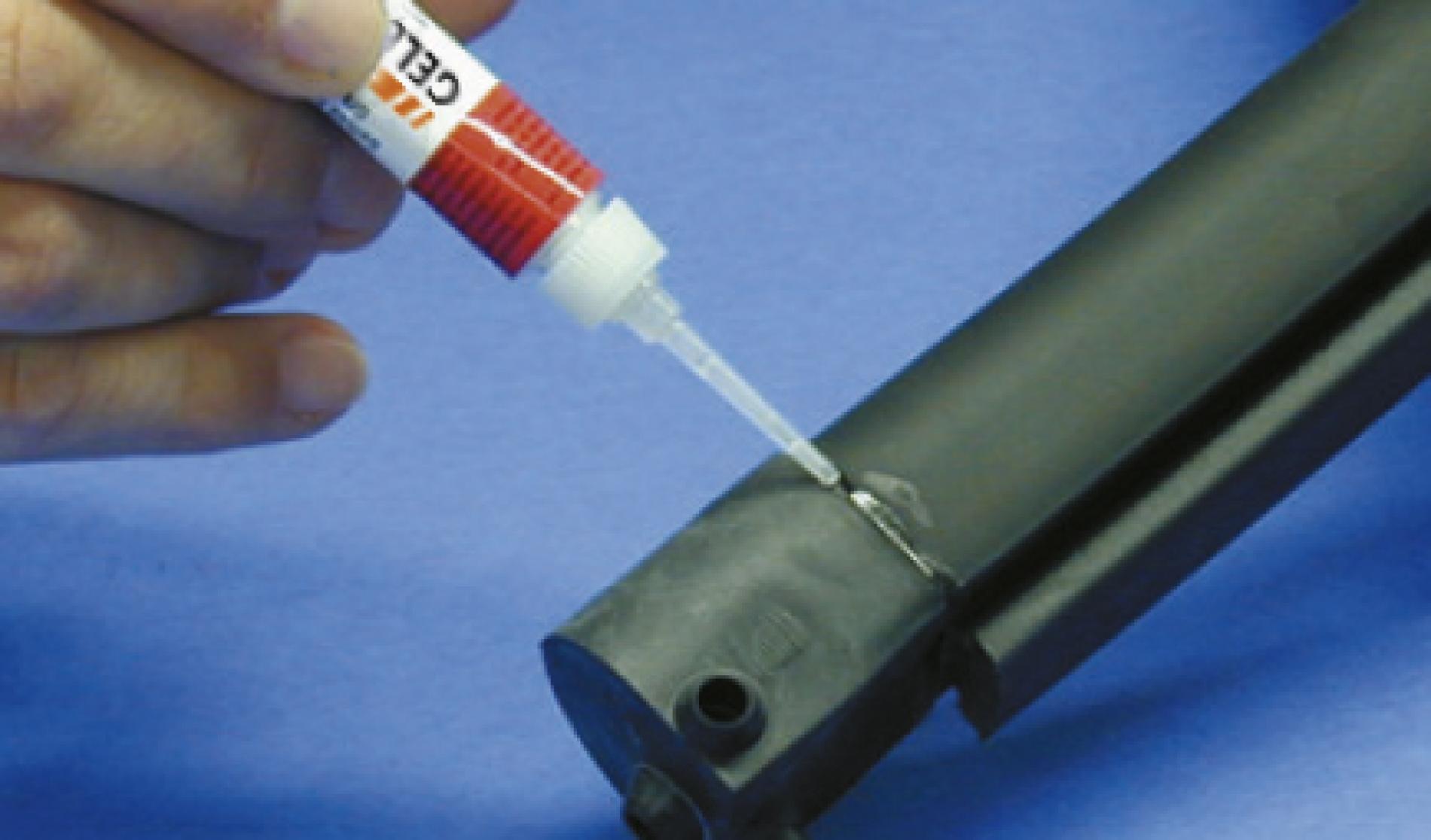
10.2 Sealing the edge at the cable bushing
Apply a thin film of adhesive to the edge of the cable bushing.
If the adhesive cracks when the dry profile is pressed together, this is only a sign that there is superfluous adhesive present.
1-4
Processing the other side of the profile
To process the other side of the profile, repeat steps 1 to 4 and then proceed from step 11.
11
Fitting the terminating plug connector (diode/resistor)
11.1 Prepunching
Use the needle of the terminating plug connector to prepunch the centre of the top and bottom copper wires (see also sections 6.1 and 6.2).
11.2 Inserting
Now insert the terminating plug connector in the prepunched copper wire.
The plug connector must be inserted in the centre of the copper wires, so as to ensure reliable contacting.
The tapering end of the plug connector must face outwards and the round side towards the switching wedge. Only in this configuration will the cap close properly.
7-10
From here, repeat steps 7 to 10.